

Design it, then make it.
Every LutraCAD design ends in a machine. The CAM module is the part that gets it there: it turns your insoles and midsoles into finished milling toolpaths or a sliced print job, inside the same software.
It is built in and included in the price, so there is no separate CAM licence to buy and no second program for your technician to learn.
Screenshot: toolpaths on the milling table
One workflow, all included
Design and toolpath live in the same file. You draw the product, choose the machine, and the file is ready to run. Change something in the design and the toolpath follows, so a correction takes a minute instead of a round trip through a second program.
Milling
Roughing and finishing toolpaths, contour cutting, two-sided milling and 4-axis output, tuned per machine and saved as a profile you can reuse.
3D printing
Automatic slicing with printers and materials that are already set up for you, so an operator picks a product and a material rather than fifty slicer settings.
Open output
Works with any open machine that reads G-code, NC, ISO or NCP. You are not tied to one supplier's hardware, and you keep the machines you already own.
Milling
Toolpaths that suit your machinePick a strategy, set your cutter and your feedrates, and the module writes the file. Offset for a clean surface, spiral for a continuous path, or parallel along the long or the short side of the block. In 2D or full 3D.
Your milling table
Set it up once, use it every dayA milling table in LutraCAD is a profile: table size, material height, where the zero point sits on each axis, the pockets in your fixture, and the start and end code your machine expects. Save it, and every job from then on lands in the right place.
Screenshot: milling table with pockets and zero point
Open by default
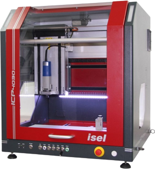
Keep the machines you ownThe module writes plain machine code, in the file format your controller expects: G-code, NC, ISO or NCP. If your machine is open, it runs. Our customers mill on ISEL machines most often, but HAAS and plenty of other brands run the same output.
Machine speaking a dialect of its own? Tell us which one. Adding a dialect is a small job at our end.
Screenshot: machine and output settings
3D printing
Slicing without the slicerChoose the printer and the material, and the software slices the design itself. The profiles behind that choice are ours: we tested them on the machine with that filament, and we keep them up to date. Your operator never has to open a slicer or work out a layer height and a temperature.


Our own slicing engine
Built for curved productsOrthopedic products are not the boxes that general slicers are written for. A shell curves in every direction, a forefoot has to flex while a heel cup does not, and a belt printer lays the whole thing down at an angle. So we wrote our own engine.
Screenshot: slice preview with density zones
Records and outsourcing
What happens around the jobCutting the shape is one part of the job. The module also keeps a production record of what you made, and lets you hand the same design to someone else when the work does not belong on your own machines.
We do not track milling blocks by batch here. If you need that level of material traceability on the printing side, the print farm software records spool, batch number and operator for every print.


Built in, instead of bolted on
General CAM packages are powerful, and a machinist who lives in one can do things we do not attempt. The trade is that they know nothing about a foot. You place the model, choose the strategy, worry about the fixture, and do it again for the next patient. Our module already knows it is looking at an insole.
| LutraCAD CAM module | Separate CAM software | |
|---|---|---|
| Where it lives | Inside the design software, on the same file | A second package, with an export step between them |
| Cost | Included in your subscription | A separate licence, often per seat |
| Who operates it | Your technician, after a short training | Someone who knows CAM |
| Knows the product | Insoles and midsoles, with the right strategy already chosen | Generic geometry, set up by you each time |
| Design change | Adjust the design, regenerate the toolpath | Export again and redo the CAM setup |
| Milling and printing | Both, from the same design and the same screen | CAM for milling, a slicer for printing, set up separately |
| Print settings | Printers and materials tested and maintained by us | Generic profiles you tune yourself |
| Machine support | Any open machine reading G-code, NC, ISO or NCP | Wide, with post-processors you configure or buy |
| Support | One party for design, toolpaths and production questions | One vendor for CAD, another for CAM |
For a car part mould, take a general CAM package. For insoles all day, this is the shorter road.
Frequently asked questions
What professionals ask us before they move their production into LutraCAD. Something else on your mind? Contact us and we will talk it through.
No. It is part of the software and included in the price. Design and production are one workflow, so we do not sell them as two products.
If the machine is open and reads G-code, NC, ISO or NCP, yes. ISEL machines are the most common among our customers, HAAS and many other brands run the same output, and there is a dedicated ISEL dialect plus 4-axis DuoCAM support. Tell us what you have and we will confirm before you buy.
No. You pick the printer and the material from a list we maintain, and the software slices with settings we tested on that combination. There is no separate slicer to open and no profile to build yourself.
Yes, and that is the point of keeping both in one module. The same design can go to the mill today and to a printer tomorrow, so you can choose per job, based on the material, the lead time or whichever machine happens to be free.
Define the pockets of your fixture in the table profile and let the module position the products for you. It fills the block, mills them in one run, and can engrave the production ID next to each one so you know which is which when they come off.
Export the design as STL and send it to your partner. That is also the route for MJF, SLS and resin printing, where the machine has its own preparation software. For Formlabs SLS the module hands the files straight to PreForm.
Yes. Each production gets its own identification and the module generates documents for your file and for the patient, filled in with your company details. We do not track material batches for milling blocks. On the printing side the print farm software does record spool and batch per print.
Curious what it does
with your machine?